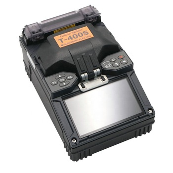
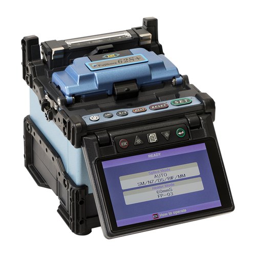
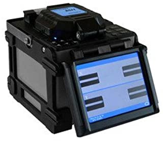
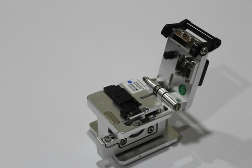
Splicing machine used to weld (fuse) two optical fibers together. This process is called fusion splicing. The fiber ends are prepared, cleaved, and placed in alignment fixtures on the fusion splicer. At the press of a button, the fiber ends are heated with electrodes, brought together, and fused.
Optical Splicing Machine
About Optical Splicing Machine
I am test text block. Click edit button to change this text.
I am test text block. Click edit button to change this text.
I am test text block. Click edit button to change this text.
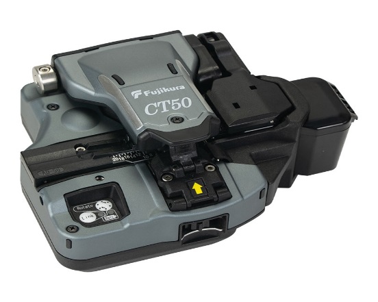
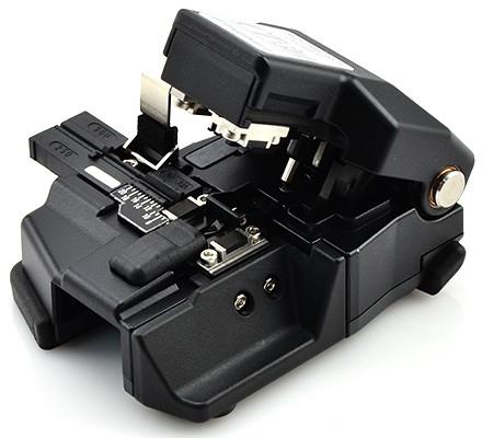
Fiber Cleaver :
The cleaver is your most valuable tool in fiber splicing. Within splicing you need the proper angle to insure proper end faces or too much light escaping into the air gaps between the two fibers will occur. The index matching gel will eliminate most of the light escape but cannot overcome a low quality cleave.
I am test text block. Click edit button to change this text.
I am test text block. Click edit button to change this text.
I am test text block. Click edit button to change this text.
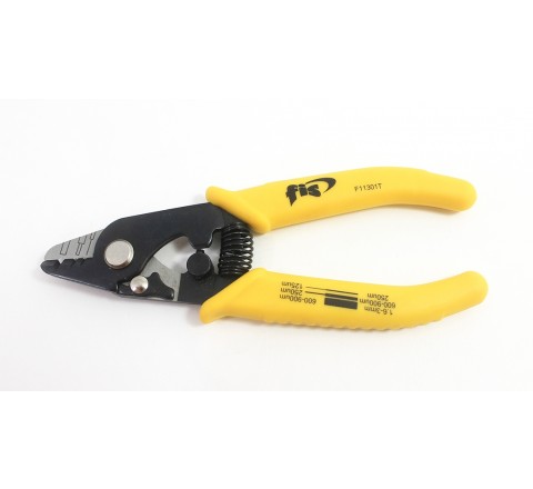
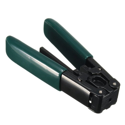
Fiber Stripper :
Fiber Stripping is the act of removing the protective polymer coating around optical fiber in preparation for fusion splicing .A fiber stripper should have hardened stripping jaws that are manufactured with tight tolerances. They assure that the fiber optic jacket strip is accurate and is removed from the cable with precision. These hand tools are made with the professional installer in mind. Handles have a ergonomic design for further precision. To make coating removal even easier our tools are preset at the factory. No further adjustments are needed. Whether it is a dual or tri jacket, thermal, tube or replacement blades the choice is yours.
I am test text block. Click edit button to change this text.
I am test text block. Click edit button to change this text.
I am test text block. Click edit button to change this text.
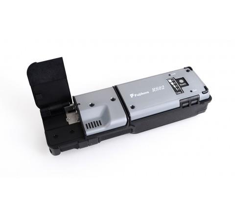
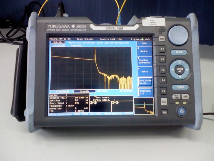
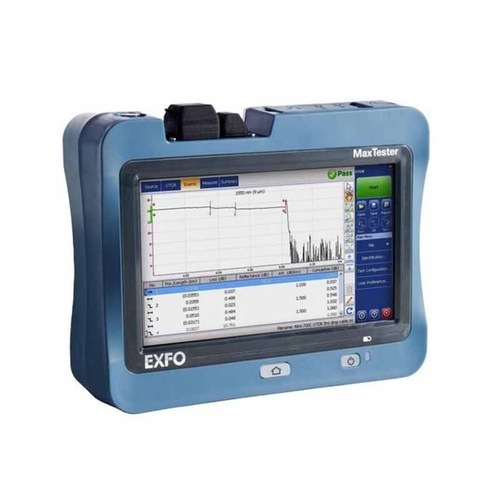
Optical time-domain reflectometer ( OTDR ) :
An optical time-domain reflectometer (OTDR) is an optoelectronic instrument used to characterize an optical fiber. An OTDR is the optical equivalent of an electronic time domain reflectometer. It injects a series of optical pulses into the fiber under test and extracts, from the same end of the fiber, light that is scattered (Rayleigh backscatter) or reflected back from points along the fiber. The scattered or reflected light that is gathered back is used to characterize the optical fiber. This is equivalent to the way that an electronic time-domain meter measures reflections caused by changes in the impedance of the cable under test. The strength of the return pulses is measured and integrated as a function of time, and plotted as a function of length of the fiber.
I am test text block. Click edit button to change this text.
I am test text block. Click edit button to change this text.
I am test text block. Click edit button to change this text.
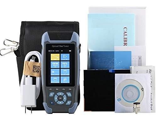
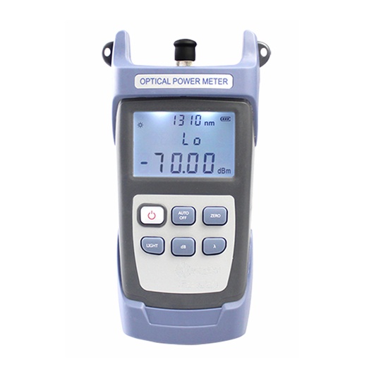
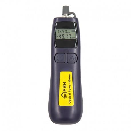
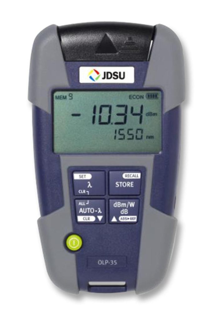
Optical Power Meter :
An optical power meter (OPM) is a device used to measure the power in an optical signal. The term usually refers to a device for testing average power in fiber optic systems. Other general purpose light power measuring devices are usually called radiometers, photometers, laser power meters (can be photodiode sensors or thermopile laser sensors), light meters or lux meters.
A typical optical power meter consists of a calibrated sensor, measuring amplifier and display. The sensor primarily consists of a photodiode selected for the appropriate range of wavelengths and power levels. On the display unit, the measured optical power and set wavelength is displayed. Power meters are calibrated using a traceable calibration standard.
A traditional optical power meter responds to a broad spectrum of light, however, the calibration is wavelength dependent. This is not normally an issue, since the test wavelength is usually known, however, it has a couple of drawbacks. Firstly, the user must set the meter to the correct test wavelength, and secondly, if there are other spurious wavelengths present, then wrong readings will result.
I am test text block. Click edit button to change this text.
I am test text block. Click edit button to change this text.
I am test text block. Click edit button to change this text.
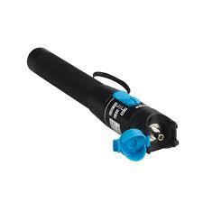
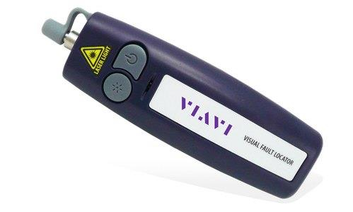
Visual Fault Locator(VFL) :
A visual fault identifier or visual fault locator (VFI / VFL) is a visible red laser designed to inject visible light energy into a fiber. Sharp bends, breaks, faulty connectors and other faults will “leak” red light allowing technicians to visually spot the defects
I am test text block. Click edit button to change this text.
I am test text block. Click edit button to change this text.